Sensei Overview and Configuration Format#
Sensei is a hardware abstraction daemon that simplifies the access to the GPIOs available on the development board, offering OSC endpoints for event reporting and control (gRPC API is under development and will be available soon).
It allows describing sensors/controllers connected to an Elk Powered Board’s GPIO through a JSON configuration file. All low level GPIO logic is taken care of by Sensei, allowing programmers to quickly connect, modify and control sensors/controllers with ease.
The low level GPIO logic or program can either be running on a separate micro-controller or the host itself, as is the case with Raspberry Pi systems. It samples the input GPIO and drives the output GPIO at a periodicity called system tick rate which is typically 1000Hz.
Sensei uses the GPIO Control Protocol to communicate with the low level GPIO logic program about information such as GPIO configuration, output GPIO values and input GPIO values.
Sensei also generates a .log file similar to Sushi for reporting run-time messages.
Example Configuration#
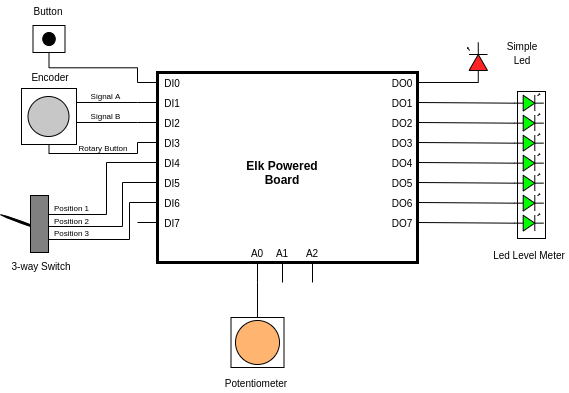
Lets consider an example Elk Powered board with 8 digital output pins numbered DO0 - DO7, 8 digital input pins numbered DI0 - DI7, and 3 analog input pins numbered A0 - A2.
It has the following connections as shown in the example schematic shown below:
An LED connected to DO0.
An LED level meter connected to DO1 - DO7.
A potentiometer connected to A0.
A button connected to DI0.
An encoder connected to DI1 - DI3.
A 3 way selector switch connected to DI4 - DI6.
The Sensei configuration for these connections would typically look like the example below.
More examples are available here. A detailed breakdown and explanations of the various fields are provided in the following sections.
{
    "backends" : [
        {
            "id" : 0,
            "enabled": true,
            "raw_input_enabled": false,
            "type" : "osc",
            "host" : "localhost",
            "port" : 23000,
            "base_path" : "/sensors",
            "base_raw_input_path" : "/raw_input"
        }
    ],

    "hw_frontend" : {
        "type" : "elk_pi"
    },

    "sensors" : [
        {
            "id" : 1,
            "enabled": true,
            "name" : "simple_led",
            "sensor_type" : "digital_output",
            "hardware" :
            {
                "hardware_type" : "digital_output_pin",
                "pins" : [0]
            }
        },
        {
            "id" : 2,
            "enabled": true,
            "name" : "led_level_meter",
            "sensor_type" : "analog_output",
            "range" : [0, 7],
            "hardware" :
            {
                "hardware_type" : "stepped_output",
                "pins" : [1,2,3,4,5,6,7]
            }
        },
        {
            "id" : 3,
            "enabled": true,
            "name" : "button",
            "sensor_type" : "digital_input",
            "inverted" : "true",
            "mode" : "on_value_changed",
            "hardware" :
            {
                "hardware_type" : "digital_input_pin",
                "polarity" : "active_low",
                "pins" : [0],
                "delta_ticks" : 1
            }
        },
        {
            "id" : 4,
            "enabled": true,
            "name" : "rotary_encoder",
            "sensor_type" : "analog_input",
            "mode" : "on_value_changed",
            "range" : [0, 15],
            "hardware" :
            {
                "hardware_type" : "encoder",
                "polarity" : "active_low",
                "pins" : [1, 2],
                "delta_ticks" : 1
            }
        },
        {
            "id" : 5,
            "enabled": true,
            "name" : "rotary_encoder_button",
            "sensor_type" : "digital_input",
            "inverted" : "true",
            "mode" : "on_value_changed",
            "hardware" :
            {
                "hardware_type" : "digital_input_pin",
                "polarity" : "active_low",
                "pins" : [3],
                "delta_ticks" : 1
            }
        },
        {
            "id" : 6,
            "enabled": true,
            "name" : "three_way_switch",
            "sensor_type" : "range_input",
            "mode" : "on_value_changed",
            "inverted" : true,
            "range" : [1, 3],
            "hardware" :
            {
                "hardware_type" : "n_way_switch",
                "pins" : [4,5,6],
                "delta_ticks" : 1
            }
          },
        {
            "id" : 7,
            "enabled": true,
            "name" : "potentiometer",
            "sensor_type" : "analog_input",
            "mode" : "on_value_changed",
            "hardware" :
            {
                "hardware_type" : "analog_input_pin",
                "pins" : [0],
                "delta_ticks" : 1,
                "adc_resolution" : 8,
                "filter_time_constant" : 0.020
            }
        }
    ]
}
Backends#
The Sensei backends represent an interface for outputting data on the host or to a network. Currently 2 backend types are implemented: Open Sound Control (OSC) and stdout.
Backends are declared using a backends json field, which is an array where you can define multiple backends. Each backend’s sub fields are described below:
id - Identification number of this backend.
enabled - Whether this backend will output data or not.
raw_input_enabled - If this is true then in addition to the processes value (clipped, scaled and possibly inverted), the unprocessed value from the sensor will also be output.
type - The type of backend, currently osc is the only recognized value, else will default to stdout.
host - The address to output osc messages to. Accepted values are localhost or an ip address. Only valid if type is osc.
port - The port used on the above host. Only valid if type is osc.
base_path - The Prefix added to OSC messages. Only valid if type is osc.
base_raw_input_path - The prefix added to OSC messages with unprocessed values. Only valid if type is osc.
Hardware Frontend#
The Hardware frontend is the type and method of connecting to the program which handles the low level logic of the sensors/controllers connected to the pins. The hw_frontend field has only one subfield which declares its type.
type - The hardware frontend type used, Currently, only two types of hardware frontend is supported:
raspa_gpio - for devices where a micro-controller is handling the GPIO logic. Sensei communicates with the micro-controller using RASPA.
elk_pi - for Elk Pi devices, where Sensei itself takes care of the GPIO logic.
Sensors/Controllers#
Sensei needs information about the sensor/controller that is connected to the pins, and how it should handle data to/from those sensors. It uses this information and informs the hardware frontend about the various sensors/controllers and the pins to which they are connected to.
For this reason, the Sensei json config file should contain the definition of:
A description of how Sensei should process the raw data from these sensors.
A description of the sensor/controller and the pin(s) to which it is attached.
All sensors are defined in a sensors array field in the json file. Each entry describes how Sensei will handle that sensor and contains a hardware subfield which declares what sensor/controller is connected.
Sensei uses an abstract representation of all sensors/controllers, which can fall into any of the following categories. All sensor values are represented as a floating point number, whose range depends on these categories:
digital_input - An input with only 2 possible values, on or off, useful for single pin button or switches. The sensor can have values 0.0 or 1.0.
range_input - An input with multiple discrete values, i.e. a multi position switch or an LED array. Its range has to be specified explicitly using the range keyword.
continuous_input - An Input from a sensor that comes “pre-processed” in floating point format.
analog_input - An sampled continuous input that is different from the range input in that it is intended to be mapped to a continuous range (0.0 to 1.0 in the case of the OSC backend) and not discrete values. This also needs the range keyword to be explicitly defined so that Sensei can normalize the sensor values. Could be potentiometers, encoders etc.
digital_output - An output that can be set on of off, like an LED. The sensor can have values 0.0 or 1.0.
range_output - An output that can accept a range of discrete values. Its range has to be specified explicitly using the range keyword.
analog_output - Similar to analog_input, this can be used to represent an output controller whose values range from 0.0 to 1.0. The range keyword needs to be explicitly defined for this type of sensor.
no_output - A “helper” sensor that doesn’t output anything on it own but controls other sensors. Look at the multiplexer section described below.
The first part of the sensors json field is a description of how Sensei will handle the sensor and its data. It contains the following fields:
id - A unique identification number of the sensor. If an id is duplicated, Sensei will log an error message stating the same.
enabled - Can be true or false. If true, values from this sensor will be sent to the output backend(s).
name - Name of this sensor, will be used if the output backend supports it.
sensor_type - Any of the sensor types as described above.
inverted - Can be true or false. If true, Sensei will invert the values. For both output and input controllers.
mode - Specifies the notification mode of an input sensor/controller. Currently supported values are:
on_value_changed - Values will be outputted only if a change in the sensor state has been detected. This is the default mode.
continuous - Values will be sent periodically according to the set tick rate.
range - This represents the range of the sensor. The following sensor_type require this explicit definition:
range_input and range_output : Values of the sensor/controller range from minimum value to maximum. In the example json config shown above, the three way switch will have values 1.0, 2.0 and 3.0.
analog_input and analog_output : Values of the sensor/controller are normalized between minimum and maximum range. In the example json config shown above, the rotary encoder has a range of 15 and so it has 15 possible values between 0.0 to 1.0.
timestamp - If true, all outputs from this sensor will be output with a timestamp. If using the OSC backend, then the signature of the output address will have an extra “t” tag at the end, containing the timestamp.
Supported Sensor/Controller Hardware#
The second part of the sensors json field is a description of the actual sensor/controller and the pins to which they are connected to. There are three major categories of controllers:
Digital Outputs : LEDs, Relays etc. Connected to the Digital Output pins of the board.
Digital Inputs : Buttons, switches, rotary encoders etc. Connected to the Digital Input pins of the board.
Analog Inputs : Pots, ribbon cables etc. Connected to the Analog Input pins of the board. All analog inputs.
The hardware section of each sensors entry in the json config declares the sensor/controller type. The following list contains the required sub fields:
hardware_type : the type of sensor/controller. The following sections explain this in greater detail.
The following hardware_type represent sensors/controllers connected to the Digital Output Pins: * digital_output_pin * stepped_output * multiplexer
The following hardware_type represent sensors/controllers connected to the Digital Input Pins:
digital_input_pin
n_way_switch
encoder
The following hardware_type represent sensors/controllers connected to the Analog Pins:
analog_input_pin
pins : An array of the pin numbers used by the controllers.
Sensei automatically figures out their pin type (Digital Output, Digital Input or Analog Input) based on the hardware_type, so it is not necessary to mention the prefix of the pin number (DO, DI, A) here.
The pins can be completely random and do not have to be contiguous.
The order of the pins is very important and will affect the behavior. Make sure that the order follows the intention of use.
It can also contain the following subfields depending on the hardware_type:
polarity : Optional field to declare the polarity of signal on the pins. This is used to determine what constitutes as an ON and OFF value of each pin. By default all controllers are active high. It can take values active_high or active_low. This is not applicable to analog_input_pin hardware type.
delta_ticks : This field allows you to set the rate of update of this sensor in terms of multiples of the system tick rate. By default, this is set to 1 for all sensors, which means they are updated every system tick. For example, when delta_ticks is 4 for an input sensor, the sensor value is read only once every 4 system ticks. Not applicable to multiplexer hardware type.
adc_resolution : Applicable only to analog_input_pin hardware types, this sets the ADC resolution for a particular sensor. By default, it is at max resolution of the on board ADC. This is particularly useful to reduce crosstalk.
filter_time_constant: Applicable only to analog_input_pin hardware types, this sets the settling time constant for a particular sensor’s digital filter. By default, the settling time is 20ms.
fast_mode : By default, all digital input pins go through software debouncing to prevent erroneous values. By setting this to true, the debouncing for a particular sensor is switched off. You can use this if you have hardware debouncing filters setup.
Digital Output Pin#
The digital_output_pin hardware type outputs its value in Little Endian binary to the pins. The minimum value possible is 0 and the maximum value is 2^(num_pins) -1. A simple example is the simple_led as shown in the example json config above.
For a digital_output_pin with a single pin connected to DO0, the sensors entry would look like this:
{
    "id" : < controller id >,
    "enabled": true,
    "name" : "< controller name >",
    "sensor_type" : "digital_output",
    "hardware" :
    {
        "hardware_type" : "digital_output_pin",
        "pins" : [0],
        "polarity" : "< active_high or active_low >",
        "delta_ticks" : < preferred delta ticks >
    }
}
For a digital_output_pin with multiple pins, lets consider and example where 4 LEDs are connected to pins DO0, DO1, DO2 and DO3. They can be the sensors entry would look like this:
{
    "id" : < controller id >,
    "enabled": true,
    "name" : "< controller name >",
    "sensor_type" : "<range_output or analog_output>",
    "hardware" :
    {
        "hardware_type" : "digital_output_pin",
        "pins" : [0,1,2,3],
        "polarity" : "< active_high or active_low >",
        "delta_ticks" : < preferred delta ticks >
    }
}
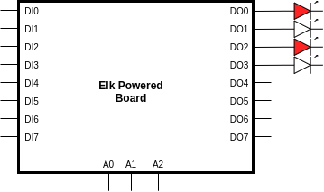
A value of 5 on this controller would result in the binary value of 5 (0101) on the output pins as shown below:
Stepped Output#
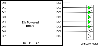
The stepped_output hardware type is suitable for LED rings or LED level meters. Its value represents the number of output pins that are ON. For example, if a controller has 7 pins and has the value of 5, the first 5 pins are set to ON and the remaining are set to OFF.
The LED level meter shown in the example schematic above is a typical use of a stepped output, whose configuration is shown below. The order of the pins dictate the start and stop pin. Note that the range specified is equal to the number of pins.
{
    "id" : < controller id >,
    "enabled": true,
    "name" : < controller name >,
    "sensor_type" : "<range_output or analog_output>",
    "range" : [0, 7],
    "hardware" :
    {
        "hardware_type" : "stepped_output",
        "pins" : [1,2,3,4,5,6,7],
        "polarity" : "< active_high or active_low >",
        "delta_ticks" : < preferred delta ticks >
    }
}
If this controller had a value had a value of 5, the LED level meter would like this:
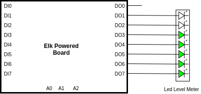
If the pins were mentioned in reverse order (”pins” : [7,6,5,4,3,2,1]) and this controller had a value of 5, the LED level meter would look like this:
Digital Input Pin#
Works similar to digital_output_pin in that it reads the binary value (Little Endian) of the pins. Depending on the polarity, this sensor detects which pin is ON or OFF. This is mostly useful for buttons and other edge trigger type of devices. The configuration for a button with a single pin connected to DI0 would look like this:
{
    "id" : < controller id >,
    "enabled": true,
    "name" : "< controller name >",
    "sensor_type" : "digital_input",
    "inverted" : "< true or false >",
    "mode" : "< on_value_changed or continuous >",
    "hardware" :
    {
        "hardware_type" : "digital_input_pin",
        "pins" : [0],
        "polarity" : "< active_low or active_high >",
        "delta_ticks" : < preferred delta ticks >
    }
}
If this button is active low, then this sensor will report a value of 1.0 when pressed and 0.0 when released.
N Way Switch#
The n_way_switch works by detecting which one of its pin is in ON state. Its value is the pin index which it detects as ON. This is only meant for multiple position switches, such as the 3 way switch in the example schematic shown above.
The order of the pins determines the value of this controller. The range should be equal to the number of pins. A typical configuration of the three way switch would like like this:
{
    "id" : < controller id >,
    "enabled": true,
    "name" : "< controller name >",
    "sensor_type" : "< range_input or analog_input >",
    "inverted" : "< true or false >",
    "mode" : "< on_value_changed or continuous >",
    "range" : [1, 3],
    "hardware" :
    {
        "hardware_type" : "n_way_switch",
        "pins" : [4, 5, 6],
        "polarity" : "< active_low or active_high >",
        "delta_ticks" : < preferred delta ticks >
    }
}
The following describes all the values of the sensor for different position of the selector switch.
For switch position 1, the active pin is DI4. The value if the sensor_type is range_input is 1.0 and for analog_input it is 0.333.
For switch position 2, the active pin is DI5. The value if the sensor_type is range_input is 2.0 and for analog_input it is 0.666.
For switch position 3, the active pin is DI6. The value if the sensor_type is range_input is 3.0 and for analog_input it is 0.999.
Encoder#
The encoder hardware type, as the name suggests, connects a rotary encoder to the digital input pins. Rotary encoders usually have two pins carrying the encoder signals: Signal A and Signal B. Optionally, some encoders also come with a button functionality as well.
The range of the encoder needs to be explicitly set in configuration and can take any values between 0 and 2^32 - 1. The pins field should have only two entries and should follow this format:
"pins" : [< signal A pin >, < signal B pin> ]
The example schematic above shows how a typical rotary encoder is connected to the pins DI1 for signal A and DI2 for signal B. Below is the typical configuration for that encoder, where it has been configured to have 32 rotation steps. It cannot have a custom delta_ticks setting as lower update speed would result in missed rotations.
{
    "id" : < controller id >,
    "enabled": true,
    "name" : "< controller name >",
    "sensor_type" : "< range_input or analog_input >",
    "inverted" : "< true or false >",
    "mode" : "< on_value_changed or continuous >",
    "range" : [0, 32],
    "hardware" :
    {
        "hardware_type" : "encoder",
        "pins" : [1, 2],
        "polarity" : "< active_low or active_high >",
    }
}
Multiplexer#
The multiplexer hardware type is a special type of controller used in situations where multiple controllers share the same pin. Consider a board with connections as shown below:
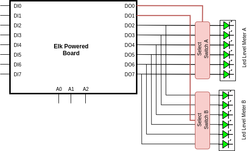
LED Level Meters A and B are both connected to the same digital output pins, i.e DO2, DO3, DO4, DO5, DO6 and DO7. LED level meter A can be switched on using Select Switch A and LED level meter B switched on using Select Switch B. Select Switches A and B are activated or enabled using digital output pins DO0 and DO1 respectively. Such a layout is common practice when number of GPIOS are limited and is usually achieved by using transistors, opto-couplers or relays.
To accommodate this, the multiplexer hardware type takes care of the switching at very high speeds. It makes sure only one of the two LED level meters are active at a given time and outputs it’s corresponding value. Now the two LED level meters can be declared as its own independent controller.
The first step is to declare a multiplexer as shown below:
{
  "id" : 1
  "enabled": true,
  "name" : "led_array_mux",
  "sensor_type" :"no_output",
  "hardware":
  {
    "hardware_type" : "multiplexer",
    "pins" : [0,1],
    "polarity" : "< active_low or active_high >"
  }
}
Since it is of type no_output, its value cannot be set and is taken care of automatically. This is needed due to the high switching speed requirement. Also note that custom delta_ticks is not supported on multiplexer hardware types.
Now you can declare the LED level meters in the config in the same way as decribed above but with the following extra information. These controllers are now “multiplexed”. 1. multiplexer_id : ID of the multiplexer controller which controls this LED level meter controller, which is 1 in this case. 2. multiplexer_pin : Pin number of the multiplexer controller which activates or switches on this LED level meter controller which is DO0 and DO1 for Led Level meters A and B respectively.
The following shows the configuration for the LED level meters A and B. Note that the range is equal to 6 as there are 6 pins used per controller. Also note that custom delta_ticks declaration for multiplexed controllers is not allowed.
{
    "id" : 2,
    "enabled": true,
    "name" : led_level_meter_A
    "sensor_type" : "<range_output or analog_output>",
    "range" : [0, 6],
    "hardware" :
    {
        "hardware_type" : "stepped_output",
        "pins" : [2,3,4,5,6,7],
        "polarity" : "< active_high or active_low >",
        "multiplexed" :
        {
            "multiplexer_id" : 1,
            "multiplexer_pin" : 0
        }
    }
},
{
    "id" : 3,
    "enabled": true,
    "name" : led_level_meter_B
    "sensor_type" : "<range_output or analog_output>",
    "range" : [0, 6],
    "hardware" :
    {
        "hardware_type" : "stepped_output",
        "pins" : [2,3,4,5,6,7],
        "polarity" : "< active_high or active_low >",
        "multiplexed" :
        {
            "multiplexer_id" : 1,
            "multiplexer_pin" : 1
        }
    }
}
Input controllers can also be multiplexed. The example below shows two 8 position switches sharing the same pins. Each 8 position switch can be read by enabling their respective select switches.
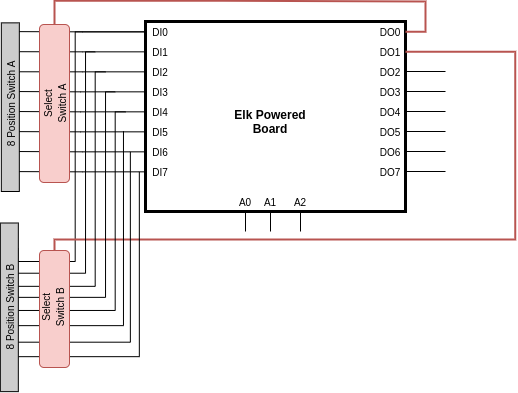
The configuration would look like this:
{
  "id" : 1
  "enabled": true,
  "name" : "led_array_mux",
  "sensor_type" :"no_output",
  "hardware":
  {
    "hardware_type" : "multiplexer",
    "pins" : [0,1],
    "polarity" : "< active_low or active_high >"
  }
},
{
    "id" : 2,
    "enabled": true,
    "name" : "8 Position Switch A",
    "sensor_type" : "< range_input or analog_input >",
    "inverted" : "< true or false >",
    "mode" : "< on_value_changed or continuous >",
    "range" : [1, 8],
    "hardware" :
    {
        "hardware_type" : "n_way_switch",
        "pins" : [0,1,2,3,4,5,6,7],
        "polarity" : "< active_low or active_high >",
        "multiplexed" :
	      {
	        "multiplexer_id" : 1,
	        "multiplexer_pin" : 0
	      }
    }
},
{
    "id" : 3,
    "enabled": true,
    "name" : "8 Position Switch B",
    "sensor_type" : "< range_input or analog_input >",
    "inverted" : "< true or false >",
    "mode" : "< on_value_changed or continuous >",
    "range" : [1, 8],
    "hardware" :
    {
        "hardware_type" : "n_way_switch",
        "pins" : [0,1,2,3,4,5,6,7],
        "polarity" : "< active_low or active_high >",
        "multiplexed" :
	      {
	        "multiplexer_id" : 1,
	        "multiplexer_pin" : 1
	      }
    }
}
The following hardware_type cannot be multiplexed
analog_input_pin
rotary_encoder